Arduino mega 2560 pinout diagram pdf wire data. This is the main controller used to program and run task for the system. The chip used in arduino 2560. Below is the pin mapping for the atmega2560. Pines pinout due arduino uno mega atmega 328 644 arduino mega 2560 pinout tft not working difference between arduino. GY-271 Module has 5 pins. The application of them is as follows: VCC: Module power supply – 3 to 5 volts; GND: Ground SCL: I2C Clock pin SDA: I2C Data pin DRDY (DataReady): When the output value of the sensor is ready, an interrupt occurs in this pin.This pin is pulled up inside the module by default. When the output value of the module is ready, the pin is “0” for 250 microseconds.
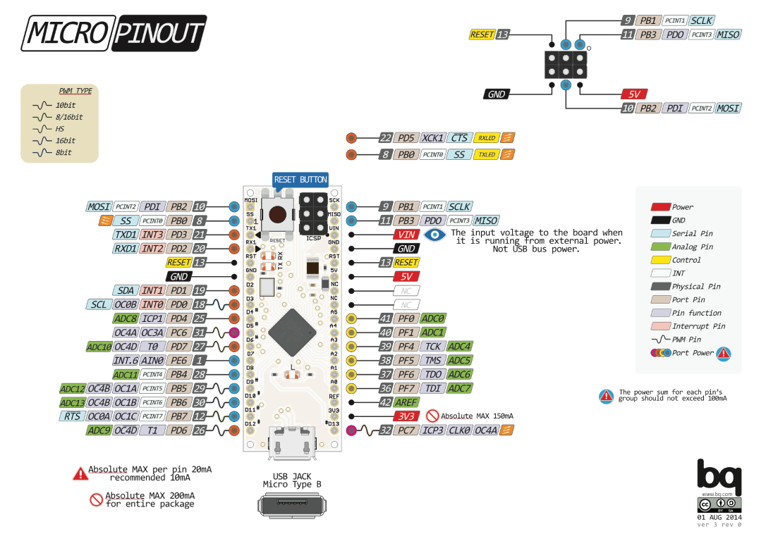
Last year I found some awesome Arduino pinout diagrams with full colour on the Arduino forums. They are all titled something like The Unofficial Arduino Pinout Diagram / The Definitive Arduino Pinout Diagram, etc. They disappeared from the Internet (pighixxx.com) in December 2013. With the help of the Internet Archive’s Wayback Machine I retrieved them. Fortunately they were distributed under a CC-BY-ND license, so here they are again in PDF’s for your download delectation.
Here’s an example bitmap version, but I recommend that you download, print and laminate the PDF version for your board.
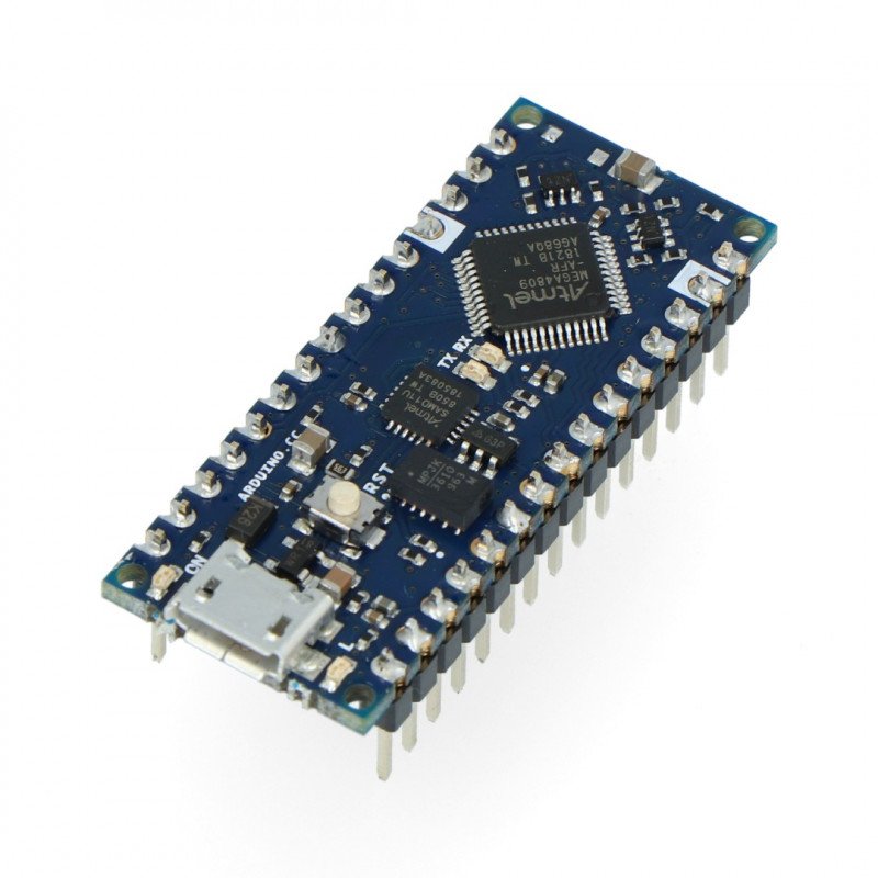
The Arduino NANO pins, similar to the UNO, is divided into digital pins, analog pins and power pins. The NANO has two more analog pins, however. There are pins with secondary functions on the table below. These secondary pins are mostly communications pins such as I2C and SPI. ATmega2560-Arduino Pin Mapping. Below is the pin mapping for the Atmega2560. The chip used in Arduino 2560. There are pin mappings to Atmega8 and Atmega 168/328 as. 2 Arduino Nano Pin Layout D1/TX (1) (30) VIN D0/RX (2) (29) GND RESET (3) (28) RESET.
Sorry, I couldn’t find any more PDF’s on the Internet Archive to host here.
Thanks, Alberto! Alberto’s writing a book, Arduino Basic Connections, but it hasn’t materialised yet, even though he’s raised quite a considerable amount of $$$. According to a tweet from him in May 2014, he’s been ill, so get well soon! It looks like it’s going to be awesomely handy, stuffed with all these pinout diagrams as well as ‘cookbook’ circuits with the same awesome graphic and detail quality and ring-bound. Fingers crossed…
Here are some other great books you might be interested in:
[amazon asin=1449313876&template=thumbnail] [amazon asin=0071784225&template=thumbnail] [amazon asin=0071771336&template=thumbnail]
Bootnote: Reader Nidal Ayari asked me to include a link to his Eagle files for Arduino Pro Mini. I haven’t even looked at them since I Don’t Do Windows (and so my PCB layout tool of choice is KiCad but I assume they’re good ;-).
Created on: 4 January 2018
How to use the photo resistor sensor module from the 37 in 1 sensor kit for Arduino from Geekcreit, Elegoo, Elektor and others. In some kits the module may be called an LDR (Light Dependent Resistor), photocell, or be written 'photoresistor'.
This tutorial shows the basic use and testing of the photo resistor sensor module with Arduino. Arduino sketches show how to read the photo resistor sensor when connected to an analog input pin.
Note that there are two different pinouts for the photo resistor sensor module, depending on which kit it is from. See the photo resistor sensor module pinout for more details.
The image below shows the photo resistor sensor module used in this tutorial.
Geekcreit Photo Resistor Sensor Module
Photo Resistor Sensor Module Circuit
Important:
Before continuing, refer to the photo resistor sensor module pinout to determine the configuration of your photo resistor sensor. There are two different photo resistor sensors.
The photo resistor module can be wired to the Arduino using the 10k resistor on the module as shown in the circuit diagrams below.
Geekcreit Photo Resistor Sensor Module Circuit
Before building the circuit, it is recommended to check your module with a multimeter to make sure which pins the 10k resistor (R1) on the module is connected to.
Photo Resistor Module Connections to Arduino:
- Pin 1 (S) of the module connects to the Arduino 5V pin.
- Pin 2 of the module connects to the Arduino GND pin.
- Pin 3 (-) of the module connects to an Arduino analog input pin. Arduino analog input A0 is used in the sketches below, but can be changed.
Geekcreit Photo Resistor Sensor Module Arduino Circuit
Alternate Photo Resistor Sensor Module Circuit

If your photo resistor module is configured with the 10k resistor connected between pins 1 and 2 of the module, then use the following circuit.
Arduino Nano Pinout Explained
Photo Resistor Module Connections to Arduino:
- Pin 1 (S) of the module connects to an Arduino analog input pin. Arduino analog input A0 is used in the sketches below, but can be changed.
- Pin 2 of the module connects to the Arduino GND pin.
- Pin 3 (-) of the module connects to the Arduino 5V pin.
Alternate Photo Resistor Sensor Module Arduino Circuit
Photo Resistor Sensor Module Arduino Sketches
Three different sketches can be found below that all use the photo resistor sensor module. All three sketches are used with the above circuits.
Photo Resistor Analog Value Arduino Sketch
The following sketch reads the analog value from the photo resistor module and sends it out of the serial/USB port of the Arduino. Use the Serial Monitor from the Arduino IDE to see the analog value.
Open the Serial Monitor window by clicking the icon at the top right of the Arduino IDE as shown in the image below and marked with a red dot.
How to Open the Arduino Serial Monitor Window
When the serial monitor window is open, make sure that the baud setting is 9600 baud as marked by the red dot at the bottom right of the above image. Values from pin A0 should be seen scrolling in the serial monitor window as shown in the image.
Light Activated LED Arduino Sketch
When the value read from the photo resistor sensor module goes below the threshold value, i.e. it becomes dark, the Arduino on-board LED is switched on. The LED is switched off when the analog value from the sensor goes above the threshold value.
Elegoo Arduino Nano Pinout
A threshold value can be selected by using the previous sketch to determine the analog value at the desired light level when the LED should be triggered. The value assigned to the threshold variable at the top of the sketch can then be set to the new value.
When the photoresistor sensor is covered, blocking most light, the on-board LED should switch on. When enough light hits the sensor, the LED should switch off.
Analog Input Arduino IDE Example Sketch

One of the example programs, called AnalogInput that comes with the Arduino IDE, can be used with the circuit in this tutorial. Find the sketch in the Arduino IDE under File → Examples → 03.Analog → AnalogInput.
Also see the Arduino Analog Input tutorial on the Arduino website that uses this sketch with a potentiometer and the above circuit from this tutorial.

The AnalogInput sketch flashes the on-board LED faster or slower, depending on the light intensity on the photoresistor module.
Donate to Starting Electronics
Elegoo Nano Pinout
Arduino Modules Tutorial
Comments are closed.